project documentation
Understanding the problem
The term automated warehouse refers to an IT driven industrial solution to massive demand for efficient low cost storage. Research in the field focused how the machinery speeds up inventory recovery with IT support that provides accurate locations and prompt searches. Within the framework of challenge, design work needs to apply the creating the machinery that moves through the aisle to a hypothetical inventory location where it removes the product and moves it to the loading access bay. The machinery will need to satisfy some or all of the movements including horizontal and vertical movement and object extraction.
The term automated warehouse refers to an IT driven industrial solution to massive demand for efficient low cost storage. Research in the field focused how the machinery speeds up inventory recovery with IT support that provides accurate locations and prompt searches. Within the framework of challenge, design work needs to apply the creating the machinery that moves through the aisle to a hypothetical inventory location where it removes the product and moves it to the loading access bay. The machinery will need to satisfy some or all of the movements including horizontal and vertical movement and object extraction.
Requirements Planning Phase
In this phase, all members collaborate on defining the problem and exploring the operating options of the available equipment and technology. As a team, we needed understand the scope of the project and how we were to create a solution.
Initial discussions surrounding viability of model construction harnessed the conceptual movement along only a horizontal path allowing the vertical movement to be considered an assumed extension of the movement process. This movement process operated through the use of a running rail/track to provide x plane movement between the shelves. Our discussions suggested the machinery could move to the hypothetical location and extract the inventory through the use of an automated arm complete with a simple claw. For modelling simplicity, the extraction would involve the arm extending into the shelf, clutching the inventory with the claw and simply retracting the arm so as to allow the inventory to be deposited onto the recovery vehicle. The vehicle can then be returned along the track for the product to be loaded at the access point.
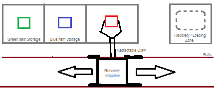
Figure 1: Concept Design
The above diagram illustrates a concept design for the proposed Automated Warehouse system. As seen, the recovery machine moves horizontally along rails along the storage shelves. The arm is able to extend and retract to retrieve items off the shelves (diagrammed as red, green and blue items for convenience) for movement onto the recovery/loading zone on the end. Theoretically, the system will also be able to work in reverse, taking an item from the loading zone and placing onto the shelf; which item is which would be ascertained through the use of a colour sensor.
User Design Phase
In this phase, the team members need to translate the understanding of the problem, equipment and technology options and broad solution parameters into a working model. This involved trial and error development that allowed the team to work towards a viable prototype design.
The next stage of the development of the Automated Warehousing System was to construct a storyboard of the system’s operation. The storyboard can be found below:

As seen in this storyboard, the first factor to note is the addition of an input and output bay (labelled as I/P O/P respectively). The input bay is for loading the item for storage, and the output bay is for requested items retrieved from storage. The first slide in the storyboard illustrates that an object is placed on the input bay ready for storage in accordance to what colour the attached colour sensor detects. The second slide shows the storage procedure for the item: it cross references the item detected with the location programmed for each object and moves along the rails to the designated location. The claw drops the item in the storage then moves back along the rails to the input bay ready for instruction; another item can be loaded for storage or an item can be taken out of storage. The third and fourth slide shows the recovery procedure: a human shows the colour sensor what item they require/desire by placing a same coloured item in front of the sensor, then the device moves along the rails to the matched storage location where the it picks it up and moves it to the output bay for retrieval. The device then moves back to the input bay for further instruction.
Construction Phase
In this phase, the team used an iterative approach in which a functional model was established and made operational. The freedom to allow the model's development to evolve functionally, was pivotal to the success of the project.
After the design work was completed, the project entered an iterative stage where frequent trials were undertaken and adjustments and modifications were completed in response to the trial results. The sequence of these trials and modifications were as follows:
After creation of the proposed system, the device needed to start being built. We started by making the drive system for the wheels: a simple wheel system with gears was made and tested for operation. I began experimenting with the colour sensor for operation of the drive system – I programmed it so when it detected a blue object, the device would play the sound “Blue!” and then move for a second. This was satisfiable as it confirmed my thoughts regarding operation.
We next started making the arm for the claw. A small rotating motor was attached to the brick to form a retractable function for the claw – it would move up and down to move the claw without hitting any objects while moving the machine. Mayank created a very suitable gear system for the claw which allowed it to be opened and closed with ease and hold a grip on a block. The design was so simple in fact that the attachment of the colour sensor was easy and very quick.
Now that the arm and claw was completed, we needed to start working on operation. The drawn up storyboard earlier was used to create the foundations of the final program: I programmed each of the buttons and used second timings to move the device from the input bay to each store, move the arm down to allow for the claw to pick up an object (not yet added nor programmed correctly), then move the device back to the exact same spot using the same timing just with a negative power on the motor.

Figure 3: Tree Diagram of Programming
This tree diagram illustrates how the programming for the AMS will work. As can be seen, the user presses a button to either store an object into, or retrieve an object from the warehouse. The colour sensor then detects what colour object it is being shown and responds appropriately – if told to store, it will first pick up the object, move to the object’s designated location, place the object in storage, then move back to the to the input bay for further operation. If told to retrieve, it will first move to the designated store, pick up the desired object, move to the output bay, place the object, then move to the input bay for further operation. The diagram also shows what motors and actuators are being used with each step.
A thing to note with this proposed system: it cannot adapt if told to store an object in a location that already has an object stored in it. However, this problem can be solved via an initial movement to the designated store to determine if an object is already in storage. If an object is already there, it can play a sound and move back to the input bay for further operation. This would be slow, but it would solve more problems than it can create – the creation of a more efficient system would involve using the touch sensors to determine if an object is in storage, this would be implemented in a further development of the project.
Currently, the actual system is completed – the arm, the wheels, the track, the claw, and the storage section are built and fully functioning. Now we just need to work on improving the building and the programming.
I decided to do some testing of the claw to see how well it actually works in the system. Our ‘rubber grip’ idea turned to not work so well in practice as the pincers in the claw are offset so it can’t pick an object up straight:

This illustration shows how the claw is offset and won’t pick an object up square. The result of this was a claw that didn’t work 80% of the time. Mayank came up with an idea to change the rubber grips with the short circle to circle connectors because on the blocks that we will have to pick up, there are protruding lines that stick out about 2mm that the connectors will catch on. The result of this changed the claw’s pick up success rate to around 70-80%. However, while there is a reasonably high success rate of picking up an object, how well it can move and place the object and how well it can replicate this, is rather random. This needs to be solved to make the system work well.
As I had a double free today split over lunch followed by IPT last, I had plenty of time to work on the robot and get it good. I decided to finally test in operation using the colour sensor, only to find that the colour sensor didn’t work as it wasn’t reflecting the colour back into the sensor because it was on an angle. I tried to fix this by putting the sensor on the top – this didn’t work either as it was getting in the way of the claw, so I decided to try putting the sensor in my original planned position: just behind the claw on the bottom. This worked and now the claw works 100% and can pick up an object based on colour.
The programming is going to be the only thing that needs to be done now. I spent a lot of time at the computer working on timings and operations, trying to make the device do what I want. The only hiccup I encountered was running the programs one after the other – I could pick up a green, blue and white block individually, but when I tried to pick them up one after the other without stopping the program, it would get stuck on one program and not operate any others. Mayank ingeniously inspected the program and discovered that the offending operation was a loop on the programming of each block; this caused the device to run the operation constantly when I only wanted it to run it once.
Now the device is working perfectly and can pick up and place a green, blue, white and yellow block in different locations. Now all that needs doing is programming the black block and the programming for the retrieval operations and trying to make my idea work of having a button press for storage operations and another button press for retrieval operations.
Post-Project Phase
While no hand-over or take-up of the working model was required, this phase looks at the hypothetical direction the project would take going forward.
This was probably the final day we would work on the system as it is now basically completed. I finished the programming for the storing with only one issue – I cannot run the black block program as the colour sensor wants to detect all colours as black for some unknown reason. So that means I can’t use the black block in the programming, however all the other blocks work fine. I also completed the retrieval programs for each block; the device can now store a block and retrieve it. I did this by using my proposed idea of pressing a button for storage and pressing another for retrieval.
The only thing that we would actually have to do on the device is fixing up the wheels. They are rather prone to bending and therefore, moving off course. This will be solved by getting Mr Russel from the woodwork dept. to make a track that fits the car perfectly. Some reinforcement of the wheels themselves would also not go astray.
For some reason, the system is quite prone to glitches now, e.g. it won’t pick up blocks properly, it won’t go straight, or it is going the wrong way. I took a look at the program and the claw, and then rectified the found issues, such as changing the power for motors to negatives or changing timings on the claw and arm; now it is working properly again like it should.
Mayank made a suggestion of changing the programming from using timings to move and determine storage locations, to using a colour sensor to detect where a spot is. This was easy enough to implement, I just had to change the drive motor from a time, to go until it detects x colour. This also worked in reverse, in that it knows where to come back to by detecting a red spot and a black spot as the input and output bays respectively.
